
Gilisymo LS53L0X i2c and Arduino Due Wire

Gilisymo LS53L0X i2c and Arduino Due Wire

In the last post, we have seen how to connect LS with Arduino with the serial interface; here I will show you how to connect Gilisymo plugin with Arduino using the i2c interface.

For more detail about the Gilisymo plugin, please visit https://gilisymo.com/.

The connection

The LS needs only four wires for this tests, +3v3, GND, SDA and SCL, connected as follow.

Note that the LS has problem in the serigraphy, the version actually available has the SDA and SCL inverted! Check the version you have before run the demo. 


The sketch

The sketch starts to search the LS plugin connected. When it founds the plugin, it saves the address in a global variable and a flag is set to avoid repeating the search.
For all the further loops, the sketch read the ranging data from LS and then wait for 100 milliseconds. The visual effect in the serial monitor is that we have a new data every 100 milliseconds indefinitely.
You can find the Source code on the following link:

Setup and I2C in Arduino

Here we use two interfaces: the serial port to output the data and the i2c interface called Wire in Arduino.
The Setup() function will initiate Serial to 115200 baud.
The Wire interface is a standard 100 khz.


Here we can see the function

                int getRangingdata(uint8_t slaveaddress)

Inside this function, we found:

Wire.requestFrom(slaveaddress, 2, RangingAddress, 1, true);

This function initiates the read over i2c interface requesting 2 bytes from RangingAddres (defined to 0xA8).
The first byte is the MSB of the ranging data and the second byte is the LSB.
The value of the ranging is returned with a simple formula:

result = b0*256+b1;


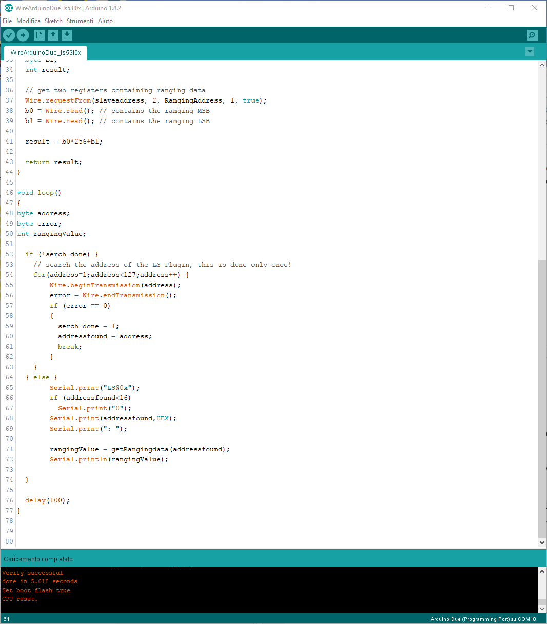
The Loop() is very easy.
On the first pass, with the help of the ‘for loop’, the sketch search for the LS plugin.
On the second pass, the sketch get data from LS plugin and print it.


The Serial Monitor output 


The Serial Plotter output


You can use more commands to customize the LS plugin, you can find them in the LS documentation:
https://gilisymo.com/content/6-documentation


Comments

Popular posts from this blog

How to program LS53L0X with ST-LINK

How to program Gilisymo LS53L0X with ST-Link Program the LS53L0X is very easy. As you already know it contains the STM32F030 a STMicroelectronics micro-controller. You can buy a ST-Link and follow the documentation  or you can use a Nucleo Board. ST-Link :  https://www.st.com/en/development-tools/st-link-v2.html All Nucleo Boards are composed of two parts: The St-link board and the micro-controller board. The ST-Link board is the little part that you can chose to separate from the micro-controller part. This little board is very useful, in fact from that board you can just use it as UART to USB converter I usually use this board to provide power at 3.3V and to control boards with serial UART, not just to program CPU. To Program the Light Saber LS53L0X I use this schema: You can find the pinout on gilisymo site :  https://www.gilisymo.com/ ST-Link from Nucleo Board Light Saber LS53L0X Signal CN4 pin 2 SWCLK pin 1
Gilisymo LS53L0X and Arduino Due This article will show you how to connect the brand new Gilisymo plugin the LS53L0X to an Arduino Due.   What is Gilisymo plugin? Gilisymo is a French company based in Grenoble, created on 2017. The first product from Gilisymo is an intelligent distance sensor the LS53L0X based on two STMicroelectronics's components: a time of flight and a stm32f030 microprocessor.  It is used on Robotics, Automations, Gesture and more. Find the Gilisymo plugin here: https://gilisymo.com/ . The LS53L0X plugin is capable to provide a distance from 3 cm to 200 cm. The difference with other distance sensors is the internal FW of the stm32f030 and the fact that when we give the power to the LS (used to simplify LS53L0X) it provides the ranging distance on the three interfaces UART, i2c and PWM. In addition, there are lot of control parameters to customize the quality of the ranging to modify the interrupt signal or to customize the PWM sig